Update (11-29-2015)
Sometimes you need a little time to search for a better solution. I changed the power supply. And now, we need only 5V voltage as input voltage, no 12V voltage are necessary.
It’s possible to operate the DC-to-DC step up converter with 5V voltage as input voltage too. ***smile***

This is the result … This is the result … with a provisional box.
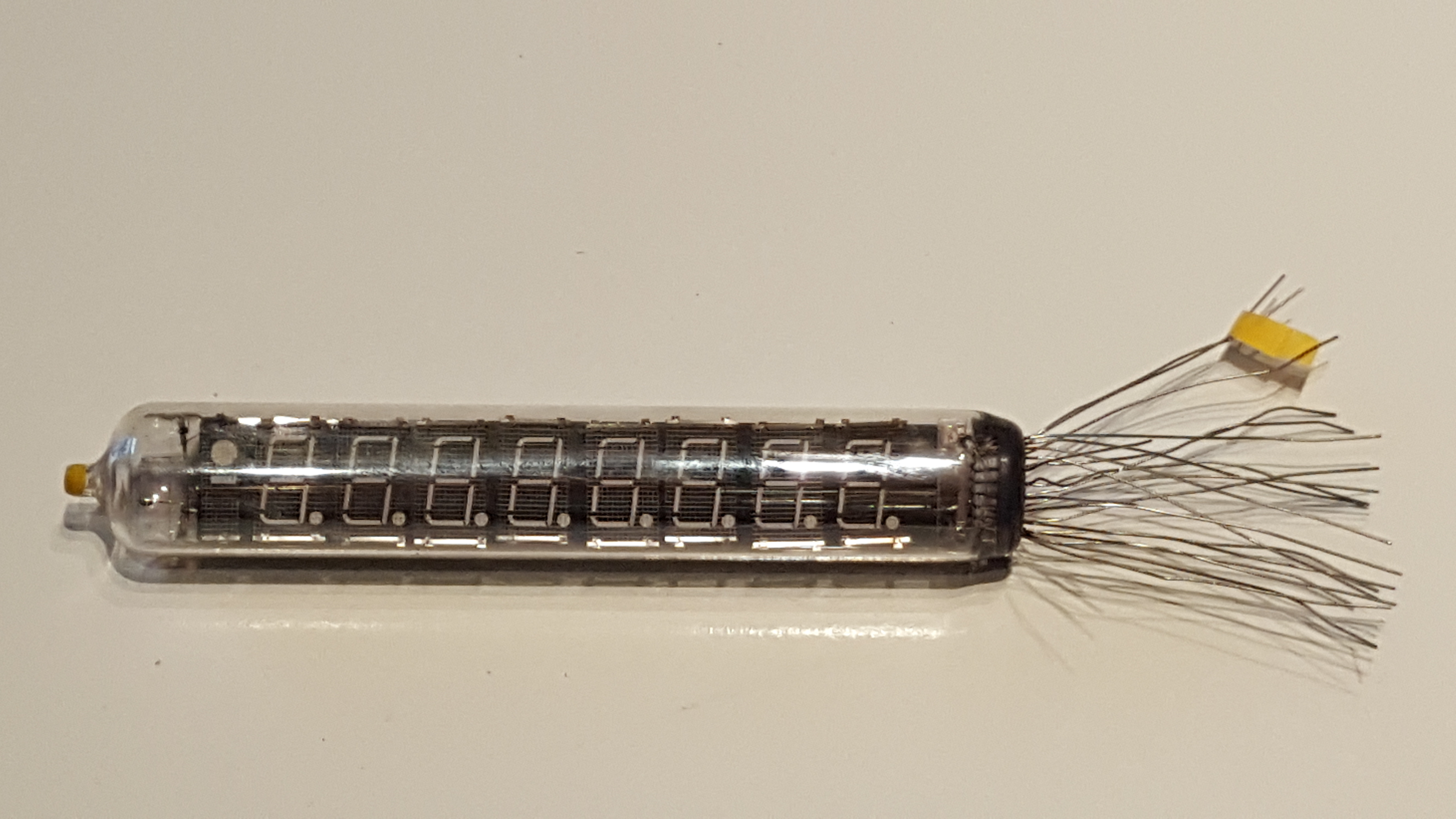
This is the tube iv-18.
You can order this via internet. I paid 18€ for two pieces.
This kind of tube works with low voltage.
What we need are 1.5 V for the filament and more or less (later more) 25 V for the grid.
I found a datasheet in the internet (www.tube-tester.com) with all the necessary informations:


Filament voltage: 5V
Filament current: 85 mA
Anode Grid voltage: 20 .. 30V
Grid current: 11 mA
You can increase the grid voltage until 50V if you use the iv-18 in multiplex mode. This should be possible, but in my project I use 28V (multiplex), not more. And the brightness is perfect.
OK, let us start to test the tube:
We need 5V for the filament (heating). Pin 1 is plus, pin 13 is GND.
And now, connect one grid pin (15 .. 22) with 26V. But you see nothing – this is correct. This are the basics. You will see something, if you connect one segment pin (3,4,5,9,10,11,12) with 26V too now. Test all the segment pins and you see if the tube works correct. You can also change the grid pin to select another digit.
Excurs:
How get I 26V DC?
It’s easy. You use a DC-to-DC-Step Up Converter. I got one from the internet, not expensive. The model name is: XTW-SY-8
Voltage (in): 3.5 .. 32V
Voltage (out): 5 .. 35V
Current (out): … 2.5A
With the potentiometer you adjust the voltage (out).

In my project, I use 12V voltage (in) and adjust 28V voltage (out).
The circuit:
OK, we need a little bit more to control the tube via arduino. The arduino give us 5V as digital out. To control with this 5V the tube (26V), we need a source driver. There are different solutions, I decide to use the UDN2981 source driver IC.

In the next picture you see the relationship between UDN2981 IC and the tube.

Basically, that’s all.
This is the whole project.
The Arduino code is normal, you know it from my other project “clock (1)”. (Do not worry, I’ll still post the source code.)
Before I finished this iv-18 clock, I built some additions.
The main problem: we need three different voltage – +5V for the Arduino, +12V as input for the DC-to-DC converter and +26V for the UDN2981 source driver IC. To realise this, I create a small additional circuit:

And the other supplement is a real time clock. I use a small module, connected via SCL / SDA. That means, I use the I2C bus. The Arduino has the I2C pins A4 (SDA) and A5 (SCL).

